DC Motors, Limit Switches, and DiodesSimple Reversible Motor Control with Limit Switches and Diodes
Our chicken coop door is controlled by an ESP8266 board running Tasmota. Tasmota allows for simple configuration of timers based on sunrise and sunset using timezone information. The door movement is achieved by a DC motor with a string, which pulls the door up. We utilize Tasmota’s Shutters and Blinds feature. The motor is controlled by a simple H-bridge (the initial version used cheap relays, but proved unreliable, especially during winter). The standard configuration of the blinds and shutters module uses time to define fully open and fully closed positions. However, this proved unreliable as the motor’s gearbox requires slightly different times depending on the outside temperature. Additionally, the system cannot easily recover from manual interventions (e.g., someone moving the door by hand).
To improve reliability, we need to add limit switches to detect fully open and fully closed positions. This will allow us to stop the motor when it reaches the limit. While signals from the switches can be wired back to GPIO pins on the ESP8266 and Tasmota can be configured to stop the motor when a switch is activated, there is a simpler solution using just two diodes.
 Motor midway through its travel
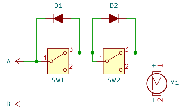
The motor’s direction is controlled by the polarity of voltage on terminals A and B. The schematic shows the door midway through its travel. Both switches are not activated, and they pass current as we have wired them in series using normally closed contacts (NC).
There are two possible states:
Ais positive andBis negative:D1is reverse biased and blocks current flow. However,SW1is not engaged, so current flows through it.D2is forward biased and allows current flow, butSW2is not engaged, so it’s irrelevant. The motor runs in one direction, towardsSW1.- When the door hits
SW1, it opens, and current stops flowing asD1blocks the current flow (sinceAis positive). The motor stops.
Ais negative andBis positive (moving in the opposite direction towardsSW2):D1is now forward biased and allows current flow, bypassingSW1.D2is reverse biased, but it doesn’t matter asSW2is closed. The motor runs in the opposite direction, towardsSW2.- When the door hits
SW2, it opens, and current stops flowing asD2blocks the current flow (sinceAis negative). The motor stops.